Stuffing Box Assembly Drawing Pdf
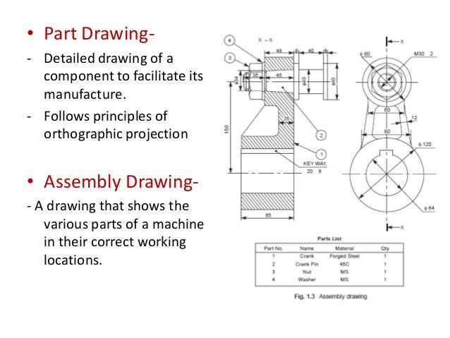
- Assembly Drawings must provide sufficient information to enable the assembly of a component. Assembly Drawings must have a number of views to show how parts fit together. Section views to show how parts fit and to eliminate hidden detail. Dimensions to indicate range of motion or overall size of assembly for reference purposes.
- How to create stuffing box in proe. 11 Mar, 2013 01:31 PM what is the best starting point in gland. 1.jpeg 2.jpeg 3.jpeg. 1 Answer Vishal Choudhury. Answered on 30 Mar, 2014 04:32 PM Here's each part and their assembly. Bodyofstuffingbox.prt.1 bush.prt.1 studofstuffingbox.prt. How to create a tailstock and stuffing box by solidworks.
Assembly and Details machine drawing pdf. 1. CHAPTER - 06 ASSEMBLY AND DETAILS DRAWING. A STEPS TO DRAW ASSEMBLY DRAWING FROM DETAILS DRAWING:- 1. Understand the purpose, principle of operation and field of application of the given machine. This will help in understanding the functional requirements of individual parts and their location. Examine thoroughly, the external and internal features of the individual parts.
Choose a proper scale for the assembly drawing. Estimate the overall dimensions of the views of the assembly drawing and make the outline blocks for each of the required view, leaving enough space between them, for indicating dimensions and adding required notes. Draw the axes of symmetry for all the views of the assembly drawing. Begin with the view from the front, by drawing first, the main parts of the machine and then adding the rest of the parts, in the sequence of assembly. Project the other required views from the view from the front complete views. Mark the location and overall dimensions and add the part numbers on the drawing. Prepare the parts list.

After the most recent edits, 'a stuffing box is an assembly which is used to house a gland seal', and 'a gland is a general type of stuffing box.' So by extension, a stuffing box is an assembly which is used to house a stuffing box. What kind of sense does that make? -Westwind273 08:35, 13 November 2010 (UTC).
This Commission, from all we can learn, appears to have performed their duties in a most satisfactory manner, so far as related to the Records then in existence in the Government and Public Offices in the city of Dublin, and the Counties and Boroughs of Ireland. We know that the Vestry or Parish Records of Wexford and Enniscorth}^ were destroyed in the unfortu- nate 3'ear of 1798, and we believe also those of New Ross and Gorey, as well as of many other parishes. Sound museum towa tei rar extractor. In the latter part of the Reign of George III., a Royal Commission was issued to examine into the state of the Public Records in Ireland. Prom their inquiries we can learn the truth concerning the Records of our County. The Commissioners apj)lied to every Public Office in Ireland, that was supposed to have the custody of any Records.

B STEPS TO DRAW PART OR DETAILS DRAWING FROM ASSEMBLY DRAWING:- 1. Understand the assembly drawing thoroughly, by referring to the parts list and the different orthographic views of the unit. Study the functional aspect of the unit as a whole. This will enable to understand the arrangement of the parts. Visualize the size and shape of the individual components. As far as possible, choose full scale for the drawing.
Rudder Stuffing Box Assembly
Small parts and complicated shapes may require the use of enlarged scales so that their presentation will have a balanced appearance. Select the minimum number of views required for describing each part completely. The view from the front selected must provide maximum information of the part. The under mentioned sequence may be followed for preparing different views of each part: (i) Draw the main centre lines and make outline blocks, using the overall dimensions of the views. (ii) Draw the main circles and arcs of the circles.

(iii) Draw the main outlines and add all the internal features. (iv) Cross-hatch the sectional views. (v) Draw the dimension lines and add dimensions and notes. Check the dimensions of the mating parts.
Simple Assembly Drawing
Prepare the parts list.